


Written by Lydea Soh and Neil Hunter.
Introduction
Safety Critical Task Analysis (SCTA) is commonly used as a tool to proactively assess and manage risk within high-hazard industries. In simple terms, an SCTA takes a high-risk task, analyses the possible failures that could occur, and prompts systemic recommendations to reduce any identified risks.
For established sites and facilities, this is useful for assessing and improving current routine operations and maintenance procedures. But SCTA doesn’t have to wait until a facility is up and running, it can usefully be applied when designing new plants and facilities, to ensure a systemic and holistic approach to the different elements of the system is considered from the foundational stages of design, rather than added on once the design is largely fixed. This is what’s known as Human Factors Engineering (HFE): the practice of integrating human factors requirements into design, with the objective of reducing the potential for human error and improving overall system performance from the outset.
Integrating Human Factors from the start of a project, rather than arriving too late to meaningfully shape anything is usually formalised in a Human Factors Integration Plan (HFIP), a document setting out what HF work will happen, when, and by whom, mapped against the project’s own lifecycle. Report 454: Human Factors Engineering in Projects sets out the recommended good practice for applying HFE consistently across the design lifecycle, on projects large and small.
This post looks at how SCTA can be built into the design process from the earliest stages, so that Human Factors is incorporated into plant design as early as possible.
The Engineering Design Lifecycle
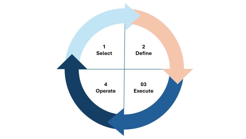
Most engineering projects move through a broadly similar set of stages:
- Select — the conceptual stage, where the fundamental approach is chosen
- Define — early design, including front-end engineering design (FEED)
- Execute — detailed design, construction and commissioning
- Operate — the plant or facility is up and running
Each stage calls for a different kind of HF input, matched to how much design detail exists at that point.
Where SCTA Fits Across The Lifecycle
SCTA works best as a thread that runs through all four stages of a project, rather than a single event bolted on at the end. For this post, we’ll focus on the Define and Execute stages, where most of the detailed design work happens, though the same approach applies just as well at Select and Operate.
At Define, SCTA is used to assess proposed plant, equipment, and layout against HF design specifications and good practice, feeding into an iterative design review process and the project’s hazard identification work.
It is acknowledged that the final design solution may not be fully mature at this stage. However, SCTA can still be used to assess the proposed design. This can provide insights into, and help refine, final design decisions. In the same way that the design process is iterative, the SCTA process should be viewed as an iterative one, which can be adapted and refined as design decisions evolve.
At Execute, the same approach carries through into the fully fleshed-out design as construction and commissioning get underway, proactively working through the possible human errors the design could allow for before the design is finalised.
How It Works
To demonstrate how SCTA could be used in the design process, we’ll use SHERPA (Systematic Human Error Reduction and Prediction Approach), our Human Factors Analysis tool.
To start the SCTA process, we construct a Hierarchical Task Analysis (HTA), which is a step-by-step breakdown of the task and the backbone for everything that follows.
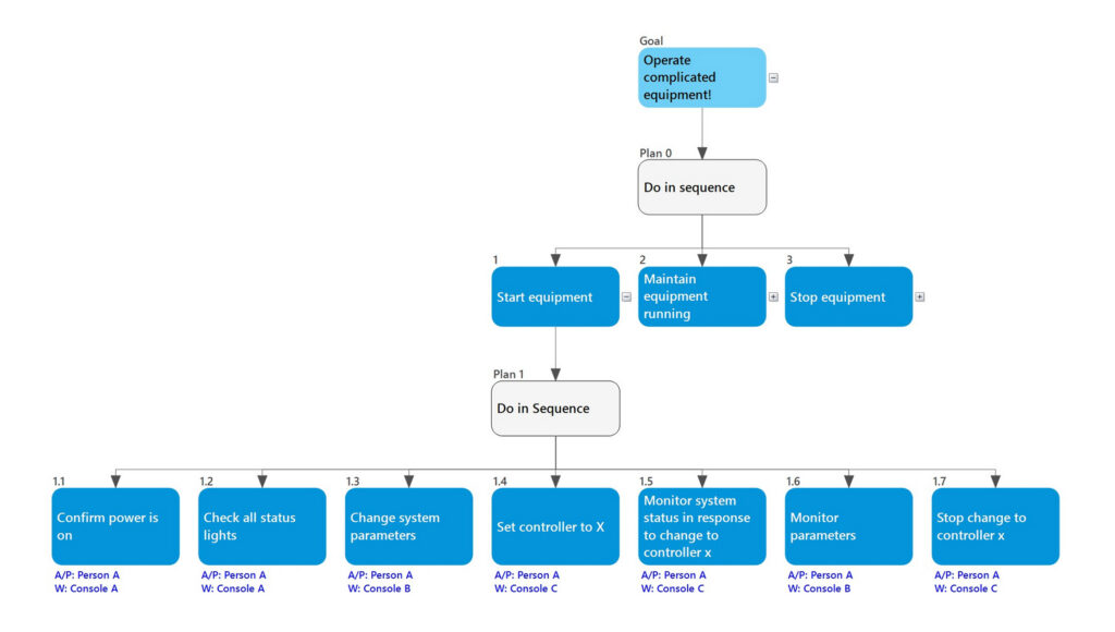
The illustrative example above shows a rough idea of what this looks like in practice. At the top level, there are three sub-steps: starting the equipment, running it, and stopping it. Each of these is then broken down further, as seen in the screenshot for the first step, Start Equipment.
With the HTA in place, the next stage is thinking through the credible failure modes for each step. Take step 1.2 in the example above, checking the status lights: here we identified three possible failure modes: a person might fail to check them at all, check the wrong lights, or do an incomplete check. Each of these has a different consequence, so each is worth capturing separately. That could look something like this.

Following through the consequences: if the status lights are omitted entirely, the operator loses their appreciation of system status altogether. If the wrong lights are checked, they come away with an incorrect appreciation of status. And if the check is incomplete, they’re left with an incomplete picture of the system state. These three outcomes affect the operator’s situational awareness differently, leading to different implications for the design.
The step-by-step structure in the data grid is also useful for ensuring good design requirements are consistently met. These recommendations would represent ‘HF requirements’ which should be added to a project issues register as design requirements which need to be incorporated into the final design. On a blank canvas you would aim to get each of these right; however, in reality, there are usually compromises to make, and the grid is where those trade-offs get recorded alongside the requirement itself.

The design requirements highlighted then feed into planning verification and validation requirements, by outlining the issues to specifically test for through user trials. Not only is this good practice, it also demonstrates that a design has been proven resilient to human error.
Seeing the task differently
Swimlane
Now that the task has been outlined and broken down, we can take this a step further and look at the allocation of function and tasks: working out who’s responsible for what across the whole process. One way of doing this is with a Swimlane diagram: a timeline of the task against location and time. This can uncover things that are not as obvious in the written analysis. A person monitoring two things at once, an unexplained gap that might mean attention could lapse, or two people’s responsibilities overlapping more than intended.
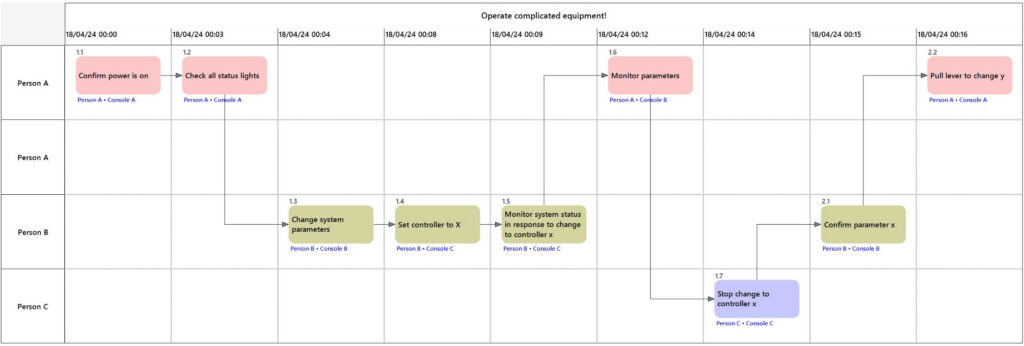
This turns out to be a genuinely useful way of bringing other disciplines into the conversation. Designers and engineers who do not understand the task can look at a timeline and see, concretely, what a design decision means for the person operating it, which tends to land better than a written description of the same risk.
Link analysis
Another thing we can do is link analysis, which is a great technique for understanding the physical space where people work. Once locations are tagged, we can lay the task analysis over a layout diagram, showing how often different locations interact with each other, and who’s interacting with what. We can use that information to inform decisions about the layout and work out the most suitable arrangement for the process involved.
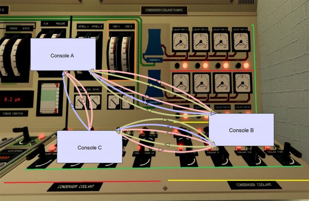
Background image sourced from https://wiki.koyot.digital/control-room.html
This is a straightforward way to spot a design that isn’t yet optimal. For instance, two elements with a lot of interaction between them but positioned at opposite ends of a layout. Flagging that early, while the layout is still a set of options rather than a poured slab, is far cheaper than discovering it once built.
Avoiding the “cliff edge”
One of the recurring problems on projects is a communication and collaboration gap between design engineers and the individuals eventually operating on the plant. Without operational input built in along the way, design decisions get made in isolation, and problems only surface once construction is finished or commissioning is underway. At that point, changes are expensive, disruptive, or simply not feasible. This abrupt, late discovery is a cliff edge, and we want to avoid this by bringing operational thinking, issues, and concerns into the process earlier, so the handover from design to operations is smooth and successful.
This is what the tools above are designed to prevent. Because HF and SCTA is integrated from the start, it gives design engineers and operations a shared point of contact well before the cliff edge is reached. SCTAs provide a structured approach to identifying problems which may increase the likelihood of human failure which could cause safety, environmental, efficiency or quality issues. This helps provide the project team with concrete, checkable requirements from the earliest stages and feed into informed design decisions rather than relying solely on the judgement or experience of the project team.
The same analysis can also form the basis of operating procedures, training, and competence requirements later in the project, saving time that would otherwise go into developing these as standalone exercises. Essential elements for ensuring people use the new process safely and efficiently. This moves into the fourth stage of the design lifecycle: Operate.
The Swimlane and Link Analysis views make that same thinking visible to designers and other members of the team, giving design and operations an opportunity to communicate while the design is still flexible enough to change.
Done early and in the ways described above, SCTA is a flexible and practical approach which delivers a range of important outputs. This is an important technique to support effective Human Factors Integration, giving design engineers something concrete to design against, and giving operators a voice in the design long before the plant is built around them.
Our consultants are seeing an increasing amount of request in this space, including alarm review and control room evaluation. Talk to our human factors team about how we can support your HFIP.
Curious how SHERPA could support your next design project? Get in touch for a demo